
how to use a multimeter To use a multimeter correctly, choose what you want to measure, select the matching dial setting, and connect the test leads to the correct input jacks. Voltage is measured across two points, resistance and continuity are checked with the power off, and current requires a different connection method.
This beginner’s guide explains the main multimeter symbols, how to read measurements, common mistakes, and how a multimeter can help with basic 12V battery and solar-power troubleshooting.
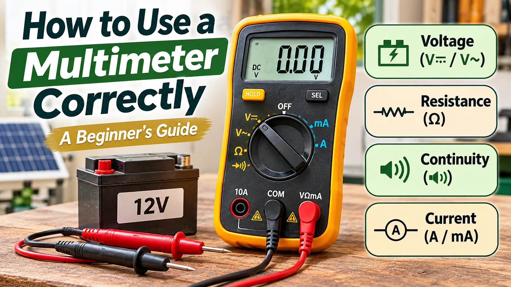
Multimeter Quick Reference
- V⎓ or V DC: Measures direct-current voltage, including typical 12V batteries.
- V~ or V AC: Measures alternating-current voltage.
- Ω: Measures electrical resistance with power removed.
- Continuity symbol: Checks whether a disconnected path has sufficiently low resistance to trigger the meter’s indicator.
- A, mA, or µA: Measures current using a supported, correctly fused input and the proper circuit arrangement.
- COM: The common jack, usually used with the black test lead.
Start with voltage, resistance, and continuity. Direct current measurements require additional precautions and should not be a beginner’s first live-circuit test.
FEATURED IMAGE: Insert the approved 1920 × 1080 educational image showing a digital multimeter, clearly identified COM and VΩ inputs, and separate symbols for voltage, resistance, continuity, and current.


What Is a Digital Multimeter?
A digital multimeter, often called a DMM, is an electronic test instrument that measures several electrical properties. Most basic models can measure AC voltage, DC voltage, and resistance. Many also offer continuity, diode testing, and current measurement.
A multimeter is useful when checking batteries, small electronic circuits, wiring connections, and some electrical equipment. For homeowners with solar or backup power systems, it can help identify certain low-voltage problems when used correctly.
Not every multimeter supports the same functions or measurement ranges. Read the manual for your exact model before using it.
Know the Parts of Your Multimeter
Before taking a measurement, identify these parts on your meter:
- Digital display: Shows the reading, units, warnings, and selected functions.
- Rotary dial: Selects voltage, resistance, continuity, current, or other functions.
- COM jack: Usually accepts the black test lead.
- VΩ input: Usually accepts the red lead for voltage, resistance, and continuity.
- mA or µA input: A current input available on some meters.
- A or 10A input: A separate current input on certain models.
- Test probes: Insulated leads used to contact test points.
Some meters share multiple functions on the same dial position. A SELECT or FUNC button may switch between them.
Critical safety rule: Never measure voltage while the red test lead is plugged into a current input marked A, mA, or µA. Depending on the meter and circuit, this can cause a short circuit, damage the instrument, or create an arc-flash hazard.
Multimeter Symbols Explained
The symbols on the dial tell you which electrical property the instrument is measuring.
| Symbol | Meaning | Typical Use |
|---|---|---|
| V⎓ | DC voltage | Batteries and DC supplies |
| V~ | AC voltage | AC electrical systems |
| Ω | Resistance | Unpowered components |
| Sound-wave icon | Continuity | Disconnected wires and switches |
| A⎓ | DC current | Approved DC current testing |
| A~ | AC current | Supported AC current testing |
| Diode symbol | Diode test | Compatible isolated components |
1. How to Measure DC Voltage With a Multimeter
DC voltage is one of the most useful measurements for small solar and battery systems. It tells you the electrical potential difference between two points.
For a beginner-friendly example, consider a single accessible, low-voltage battery whose terminals and test procedure are documented by its manufacturer.
Step-by-Step DC Voltage Measurement
- Check the battery identification, expected voltage, meter rating, and safe testing instructions.
- Inspect the probes, insulation, input jacks, and meter case for damage.
- Connect the black lead to COM and the red lead to the VΩ input.
- Set the meter to DC voltage, marked V⎓ or V DC.
- For a manual-ranging meter, select an appropriate range above the expected voltage.
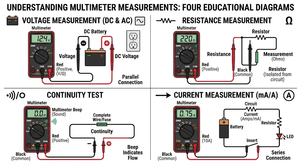
- If the manufacturer’s test procedure allows it, place the black probe on the negative terminal and the red probe on the positive terminal, keeping the probe tips apart.
- Read the voltage and units displayed on the screen, then remove the probes safely.
Voltage is measured in parallel, across the two test points. The meter does not need to become part of the normal load-current path.
If a negative sign appears during a DC voltage measurement, the probes may be reversed relative to the measured polarity. Confirm the setup and follow the device instructions.
What Does a 12V Battery Reading Mean?
A battery marked 12V will not necessarily display exactly 12.00 volts. Its measured terminal voltage depends on battery chemistry, state of charge, temperature, recent charging, and connected loads.
A single voltage measurement does not provide a precise state-of-charge percentage for every battery type. Check the battery manufacturer’s voltage specifications and monitoring recommendations.
2. How to Measure AC Voltage
Alternating-current voltage changes polarity over time. It is found in household AC systems and at the AC output of many inverters.
For AC voltage, the meter typically uses the V~ setting. The black lead normally goes to COM, and the red lead goes to the voltage input. The meter must be suitable for the installation’s voltage, measurement category, and environmental conditions.
AC voltage hazard: Household outlets, breaker panels, inverter AC terminals, and other energized equipment can cause serious injury or death. Beginners should not probe exposed mains wiring or open inverter enclosures. Have these measurements performed by a qualified electrical professional.
For learning purposes, practice identifying the AC voltage symbol and input jacks on an unplugged meter. Do not use a household outlet as your first test circuit.
3. How to Measure Resistance (Ohms)
Resistance describes how strongly a material or component opposes electrical current. A multimeter displays resistance in ohms, marked by the symbol Ω.
A resistor, for example, can be checked against its rated resistance when safely isolated from other powered components.
Steps for Resistance Testing
- Disconnect the circuit from all sources of power, including batteries and solar inputs.
- Follow the equipment instructions for safely discharging stored energy.
- Verify that the circuit is de-energized using an appropriate method and meter.
- Isolate the component if other circuit paths could change the reading.
- Connect the black lead to COM and the red lead to the Ω input.
- Select the resistance setting.
- Place the probes across the isolated component and read the value.
For example, a correctly identified 1,000-ohm resistor might display a value near 1 kΩ within its specified tolerance.
A display reading such as OL may indicate a value above the selected range or an open circuit, depending on the meter and test setup. Check the manual before interpreting the result.
Remember: Resistance testing is for de-energized circuits. A resistance reading can also be affected by other components connected in parallel.
4. How to Test Continuity
A continuity test helps determine whether a disconnected electrical path has sufficiently low resistance for the meter to recognize it as continuous.
It is often used to check an isolated wire, switch, or connection. Many meters produce a beep when the measured resistance falls below a model-specific threshold.
Continuity Test Steps
- Completely disconnect the test path from power and other connected circuits.
- Verify the circuit is de-energized and stored energy has been safely removed.
- Insert the black lead into COM and the red lead into the continuity-compatible input.
- Select the continuity setting, usually marked with a sound-wave symbol.
- Touch the probes together to confirm the test function responds as expected.
- Place the probes at opposite ends of the isolated conductor or component.
- Read the display and note whether the meter sounds its continuity indicator.
A beep usually indicates resistance below the instrument’s continuity threshold. No beep may mean an open circuit, high resistance, or an unsuitable contact. The meaning depends on the meter.
A continuity beep does not prove that a wire can safely carry its intended operating current.
IMAGE 2: Insert the approved 1200 × 1500 image showing safe multimeter settings, an isolated resistor, an unpowered continuity test, and a small 12V battery voltage check.
5. How Current Measurement Works
Current is the flow of electrical charge and is measured in amperes (A), milliamperes (mA), or microamperes (µA).
Unlike voltage measurements, direct current measurement with standard meter probes usually requires the instrument to be placed in series with the circuit. This means the circuit’s current flows through the meter’s internal current-measuring path.
The current input must be correctly rated and protected. Some meters have a dedicated mA input and a separate A input. Others support only certain current types or ranges.
Current measurement warning: Never place a meter in current mode directly across battery terminals, a power supply, or an electrical outlet. That can create a short circuit. Never open a live circuit to insert a meter. Power must be removed before a properly trained person configures an approved series-current test.
For many solar and battery troubleshooting tasks, an appropriately rated DC clamp meter is a better option because it can measure current around a conductor without interrupting the circuit. The correct clamp type and measurement rating still matter.
Do not use a handheld multimeter’s current input to measure high-current battery, inverter, or solar-array circuits unless the complete procedure has been designed and approved by a qualified professional.
How to Use a Multimeter for Solar and Battery Systems
Multimeters are useful for understanding some low-voltage electrical conditions in off-grid systems. However, the equipment’s design determines which measurement points are safe to access.
Checking an Accessible 12V Battery
If the battery manufacturer allows direct terminal-voltage measurement, a correctly rated meter in DC voltage mode can show the voltage across the positive and negative battery terminals.
Use the correct voltage input and avoid shorting the terminals with a probe, tool, or jewelry. Large batteries can deliver extremely high fault currents even at relatively low voltages.
Do not disconnect charging cables or battery management connections just to obtain a reading unless the equipment instructions specifically require it.
Checking Solar Panel Voltage
Solar panels produce DC voltage when exposed to light. Their voltage may be considerably higher than the nominal battery voltage, particularly when panels are connected in series.
The panel or string’s specified open-circuit voltage, temperature conditions, connector type, and test equipment ratings must be checked before any measurement.
Do not disconnect energized solar connectors or probe exposed PV wiring as a beginner. Solar strings can remain energized in daylight and may present dangerous DC voltage. Use a qualified solar technician for PV string measurements or suspected faults.
Checking an Inverter
An inverter changes DC power into AC power. Depending on the model, its battery input and AC output can have different voltage levels and safety requirements.
Do not open an inverter enclosure or probe internal terminals. Capacitors may retain hazardous energy after the equipment has been disconnected.
Begin with the inverter’s display, fault codes, and manufacturer-approved external checks. Have internal electrical testing performed by a qualified professional.
For related background, read the SoloPwr solar panel battery connection guide.
Multimeter Safety Ratings: What CAT II, CAT III, and CAT IV Mean
Not all multimeters are suitable for every electrical environment. A measurement-category rating helps identify the level of protection a meter is designed to provide against certain electrical transients.
| Rating | General Environment |
|---|---|
| CAT II | Certain plug-connected loads and equipment |
| CAT III | Fixed building electrical distribution |
| CAT IV | Electrical service entrance and source-of-installation environments |
Use test leads with ratings suitable for the meter and measurement environment. A damaged or unsuitable lead can compromise the safety of an otherwise capable instrument.
For an explanation of these ratings, consult Fluke’s guide to digital multimeter safety.
Common Multimeter Mistakes
- Using the wrong dial setting: AC voltage, DC voltage, resistance, and current are different functions.
- Leaving the red lead in the current jack: This can cause a dangerous short when the probes contact a voltage source.
- Measuring resistance on an energized circuit: Remove power and verify the circuit is safe first.
- Ignoring stored energy: Capacitors and batteries may remain hazardous after other equipment is turned off.
- Choosing the wrong range: Manual-ranging meters must be set appropriately for the expected value.
- Touching exposed probe tips: Fingers should remain behind the insulated finger guards.
- Ignoring meter ratings: Test leads, fuses, and CAT ratings matter.
- Using a damaged meter: Cracked cases, worn insulation, and loose input jacks are reasons to stop testing.
What Do Common Multimeter Display Readings Mean?
| Display | Possible Meaning |
|---|---|
| 0.00 V | Little or no measured voltage, or an issue with the test setup |
| Negative DC reading | Measured polarity is opposite to the probe reference |
| OL | Over-range or open circuit, depending on mode |
| 0.0 Ω or low Ω | Low resistance between the test points |
| kΩ | Thousands of ohms |
| MΩ | Millions of ohms |
| Low battery symbol | The meter battery may require replacement |
Frequently Asked Questions
What setting should I use to test a 12V battery?
Use DC voltage mode on a suitably rated meter, with the probes connected to the correct voltage inputs. Follow the battery manufacturer’s safe testing instructions.
What is the difference between voltage and current?
Voltage is the electrical potential difference between two points. Current is the flow of electrical charge through a circuit. They require different meter connections.
Can I check continuity with the power on?
No. Disconnect the circuit from all power sources, verify it is de-energized, and follow the equipment’s stored-energy precautions before using continuity mode.
Does every multimeter measure AC current?
No. Some basic multimeters measure only DC current, while others support both AC and DC current. Check your model’s specifications.
Can I measure solar panel current with a regular multimeter?
Not automatically. Solar panel current tests require an approved procedure and properly rated equipment. High-current PV circuits and battery systems can be dangerous. A qualified solar technician can select suitable test equipment and methods.
Why does my multimeter beep in continuity mode?
The beep normally indicates that the measured resistance is below the meter’s selected threshold. That threshold varies by model, so a beep does not necessarily mean zero resistance.
Multimeter Safety Checklist
- Read the manual for the exact meter model.
- Inspect the meter, probes, and cable insulation.
- Verify operation using an appropriate known source or proving device.
- Choose the correct measurement function and range.
- Confirm the correct input jacks before every measurement.
- Keep fingers behind probe guards.
- Disconnect power before resistance and continuity tests.
- Account for batteries, capacitors, and other stored energy.
- Never put a current input directly across a voltage source.
- Use an appropriately rated meter for the electrical environment.
- Leave exposed mains, high-energy battery, inverter, and PV string testing to qualified professionals.
- Return the red probe to the voltage input after any approved current measurement.
The Best Way to Learn Multimeter Basics
Start by learning the meter’s symbols, input jacks, and safety ratings. Practice resistance and continuity measurements on safely isolated components, then learn basic low-voltage DC measurements using equipment approved for beginner use.
Remember the main differences: voltage is measured across two points, resistance and continuity require power to be removed, and current measurement needs a properly rated series connection or suitable current probe.
For solar and backup-power work, knowing when not to probe a circuit is just as important as knowing which dial setting to select.
Technical references: Fluke: How to Use a Multimeter, Fluke: Digital Multimeter Safety, Fluke: Resistance Measurement, and Klein Tools: MM325 Specifications. Follow the instructions and safety limits for your specific instrument.