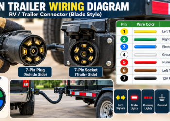

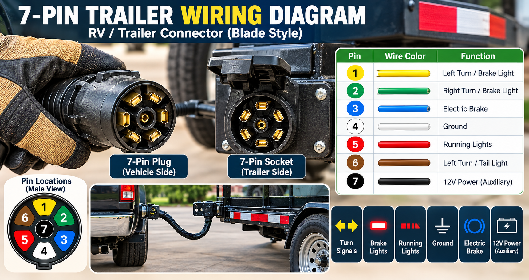
A 7-pin trailer wiring diagram shows how a tow vehicle connects to a trailer’s lights, electric brakes, ground, and 12V auxiliary power. Most 7-way RV blade connectors support seven circuit functions, but the wire colors are not always the same.
Before connecting any wires, identify your connector type and check the manufacturer’s diagram. This guide explains the seven functions, compares common color codes, and covers safe ways to check trailer wiring problems.
7-Pin Trailer Wiring: Quick Reference
A standard 7-way RV blade connection commonly provides these seven functions:
- Ground: Electrical return path.
- Tail and marker lights: Running, clearance, and side lights.
- Left turn and stop: Left-side signal and brake lamp.
- Right turn and stop: Right-side signal and brake lamp.
- Electric brakes: Controlled braking output, if equipped.
- 12V auxiliary: Additional electrical power, if supported.
- Reverse: Backup lights or another designated function, if equipped.
Remember: These are circuit functions, not universal pin numbers or wire colors.
Featured Image: Insert a verified 7-way RV blade connector diagram here. The illustration should clearly distinguish circuit functions and should not use unsupported numbered terminal positions.
What Is a 7-Pin Trailer Connector?
A 7-pin trailer connector, also called a 7-way connector, carries electrical signals and power between a tow vehicle and a trailer. It supports the main exterior lighting circuits and may also provide connections for electric trailer brakes and auxiliary power.
Travel trailers, campers, equipment trailers, and some utility trailers use 7-way connectors. However, not every seven-contact connector has the same physical design or wiring configuration.
7-Way RV Blade vs. 7-Way Round Pin
A 7-way RV blade connector has flat electrical contacts. A 7-way round-pin connector uses round contacts in a different arrangement.
These connectors are not directly interchangeable. A suitable adapter or correctly matched connector is required.
Important safety note: Never connect wires based only on a picture that does not identify the connector model, terminal layout, and viewing direction. A plug shown from the wiring side can appear mirrored compared with the contact side.
7-Pin Trailer Wiring Color Code
Trailer wiring colors can differ between manufacturers and wiring conventions. This is one reason two diagrams found online may show different colors for the same function.
CURT and Lippert document traditional RV blade and SAE J2863 configurations. The table below compares common colors for the seven functions.
| Function | Traditional RV | SAE J2863 |
|---|---|---|
| Ground | White | White |
| Tail / running lights | Green | Brown |
| Left turn / stop | Red | Yellow |
| Right turn / stop | Brown | Green |
| Electric brakes | Blue | Blue |
| 12V auxiliary | Black | Orange |
| Reverse lights | Yellow | Gray |
Notice that green may identify running lights in traditional RV wiring but right turn and stop lights in an SAE J2863 configuration. Yellow can also represent different functions.
Always verify your actual connector and harness. A previous repair may also have changed the wire colors.
For manufacturer references, see the CURT trailer wiring guide and the Lippert trailer wiring guide.
What Each 7-Pin Trailer Wire Does
1. Ground Wire
The ground circuit provides an electrical return path for the trailer equipment. White is the common ground color in both configurations shown above.
A weak ground connection can cause dim lights, flickering, or several lamps operating incorrectly at the same time.
Ground connections should be secure, clean, and installed according to the manufacturer’s instructions. Do not rely on the hitch ball as the trailer’s only electrical ground path.
2. Tail and Running Lights
The running-light circuit powers the trailer’s tail lights, side markers, clearance lights, and license plate lights where fitted.
These lights normally operate with the tow vehicle’s parking lights or headlights.
Traditional RV blade wiring commonly uses green. SAE J2863 commonly uses brown.
3. Left Turn and Stop Lights
On a typical North American combined stop-and-turn lighting system, this circuit controls the left turn signal and left brake lamp.
Traditional RV blade wiring commonly uses red, while SAE J2863 commonly uses yellow.
4. Right Turn and Stop Lights
The right-side circuit operates the trailer’s right turn signal and brake lamp on combined lighting systems.
Traditional RV blade wiring commonly uses brown. SAE J2863 commonly uses green.
Trailers with separate brake and turn signals may require a suitable converter or another approved wiring arrangement.
5. Electric Trailer Brakes
The electric brake circuit carries controlled output from a compatible trailer brake controller to the trailer’s electric braking system.
Blue is the common electric brake wire color in both RV blade configurations shown in the table. However, the actual terminal and conductor must still be verified.
Electric brake safety: Never connect trailer brake magnets directly to a stop-light wire or an unregulated 12V power source. Electric trailer brakes require compatible brake-control equipment and manufacturer-approved installation. The emergency breakaway system must also operate correctly.
6. 12V Auxiliary Power
The auxiliary circuit can supply 12-volt electrical power from the tow vehicle to supported trailer equipment.
The tow vehicle may require specific fuses, relays, or other equipment before this circuit is active.
Traditional RV blade wiring commonly uses black for auxiliary power. SAE J2863 commonly uses orange.
The available power is limited by the vehicle’s electrical design. This connection should not be treated as an unlimited accessory supply or a complete RV battery charger.
7. Reverse Lights
The reverse circuit may operate trailer backup lights or another manufacturer-approved reverse-related function.
Some trailers do not use this circuit. Traditional RV blade wiring commonly uses yellow, while SAE J2863 commonly uses gray.
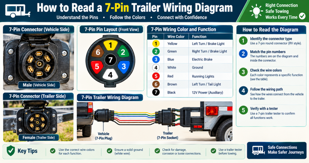
How to Read a 7-Pin Trailer Wiring Diagram
A wiring diagram is useful only if it matches the connector you have. Use the following checks before relying on a diagram.
- Identify the connector type. Check whether it uses RV blade or round-pin contacts.
- Check the viewing direction. A diagram viewed from the terminal side may be mirrored compared with the connector face.
- Read the manufacturer’s labels. Match terminals to the actual connector instructions.
- Confirm each circuit function. Do not depend only on wire colors.
- Identify optional circuits. Some trailers do not have reverse lights, electric brakes, or active auxiliary power.
- Verify before making connections. Use appropriate test equipment and approved procedures.
A picture that labels wires from 1 through 7 without showing the exact connector terminal positions is not a reliable installation diagram.
How to Check a 7-Pin Trailer Connection
When trailer lights or electrical equipment stop working, start with basic inspection and circuit checks before replacing components.
Step 1: Inspect the Plug and Socket
Park the vehicle and trailer safely, secure them against movement, and turn off the electrical circuits before inspecting the connectors.
Look for corrosion, bent contacts, moisture, damaged insulation, loose parts, or broken cables.
Step 2: Test the Lighting Functions
Use a compatible 7-way trailer tester according to its manufacturer’s instructions. Check running lights, left and right turn signals, and brake lights individually.
If another person operates the tow vehicle controls, stay clear of moving equipment and never stand between the tow vehicle and trailer.
Step 3: Check the Ground Connection
Flickering lights, dim lamps, or unexpected lighting behavior may indicate a poor ground or connector fault.
Inspect the ground wiring and connections. Perform continuity or resistance checks only when the relevant circuits are safely de-energized and the equipment instructions permit them.
Step 4: Check Auxiliary Power
If the 12V auxiliary circuit is not working, check the tow vehicle documentation to confirm that the circuit is installed and determine when it should be active.
Do not bypass circuit protection or apply battery power to an unidentified terminal.
Step 5: Verify the Electric Brakes
Trailer brake systems require their own checks. Working brake lights do not prove that the electric trailer brakes are operating correctly.
Follow the trailer and brake controller manufacturer’s procedures for checking braking performance and the breakaway system.
If the electric brakes are weak, intermittent, or not operating, have the system inspected by a qualified technician before towing.
Common 7-Pin Trailer Wiring Problems
| Problem | Possible Cause | What to Check |
|---|---|---|
| No trailer lights | Plug, ground, or vehicle output fault | Connector and lighting circuits |
| Wrong lights operate | Incorrect circuit connections | Manufacturer diagram |
| Flickering lights | Corrosion or poor ground | Ground and contacts |
| No electric brakes | Controller, wiring, or brake fault | Professional brake inspection |
| No 12V power | Inactive circuit, fuse, or wiring fault | Vehicle documentation |
| No reverse lights | Unused circuit or lighting fault | Reverse circuit and equipment |
These are possible causes rather than confirmed diagnoses. Several different faults can create similar symptoms.
7-Pin Trailer Wiring and RV Solar Power
Travel trailers and campers often have two electrical systems that owners should understand separately: the towing connection and the RV house-power system.
The 7-way connector handles exterior lights, electric brake output, and a limited auxiliary power connection. An RV solar system uses panels, a compatible charge controller, batteries, protection equipment, and electrical distribution components.
RV power tip: The tow vehicle’s 12V auxiliary connection is not automatically a complete battery charging system. Voltage drop, current limits, cable size, battery chemistry, and charging equipment all matter. Some installations use an appropriately rated DC-to-DC charger.
Do not connect solar panel output directly to an unidentified 7-way terminal. Do not use the trailer brake circuit for battery charging.
For a separate guide to solar charging, read the SoloPwr solar panel battery connection guide.
Common Trailer Wiring Mistakes to Avoid
- Assuming every color code is the same: Different connector systems may use different colors.
- Confusing plug and socket views: Connector layouts can appear mirrored.
- Using the wrong connector diagram: RV blade and round-pin types differ.
- Ignoring the ground path: Poor grounds can cause several lighting problems.
- Connecting electric brakes incorrectly: Brake circuits require compatible control equipment.
- Overloading the auxiliary circuit: Electrical protection and current limits must be respected.
- Skipping final testing: Required lighting and braking functions must work before towing.
Frequently Asked Questions
Are all 7-pin trailer wiring diagrams the same?
No. Connector types, terminal views, and wire color conventions can differ. Always identify the correct connector before following a wiring diagram.
What color is the electric brake wire?
Blue is the common electric brake conductor in both traditional RV blade and SAE J2863 configurations discussed here. Verify the actual function on your connector before making a connection.
What does the white trailer wire do?
White commonly identifies the ground circuit in the RV blade configurations described here. The ground connection provides the electrical return path.
Can a 7-pin trailer connector charge a camper battery?
A supported auxiliary circuit may provide power that contributes to charging. However, correct charging depends on the vehicle, battery, wiring, and charging equipment. A dedicated DC-to-DC charger may be needed.
Why do my trailer lights work but the electric brakes do not?
Lighting and electric brake circuits are separate. Working lights do not confirm that the brake controller, brake wiring, or trailer brakes are working correctly. Have the brake system checked before towing.
Can I follow a Pinterest trailer wiring diagram?
Use a Pinterest diagram only as an introductory visual reference. It may show different wire colors, incorrect terminal assignments, or an unclear viewing direction. Always check the manufacturer’s wiring documentation.
Final Trailer Wiring Safety Checklist
- Confirm the connector type.
- Check the correct terminal-view orientation.
- Verify each circuit with manufacturer documentation.
- Inspect the plug, cable insulation, and ground connections.
- Test required running, stop, and turn lights.
- Check auxiliary and reverse functions if equipped.
- Verify electric brakes and the breakaway system.
- Do not tow with unresolved lighting or braking problems.
A good 7-pin trailer wiring diagram explains the functions of the connector and makes it easier to understand lighting, brakes, and power circuits. But the most important step is confirming the actual wiring before connecting or replacing electrical components.
Use the color chart as a reference, check the correct manufacturer diagram, and test the required functions before towing.
7-Pin Trailer Wiring Diagram: Colors & Functions
Technical references: CURT Trailer Wiring Guide and Lippert Trailer Wiring Guide. Always follow the product-specific documentation for your tow vehicle, connector, and trailer.