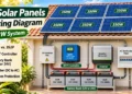

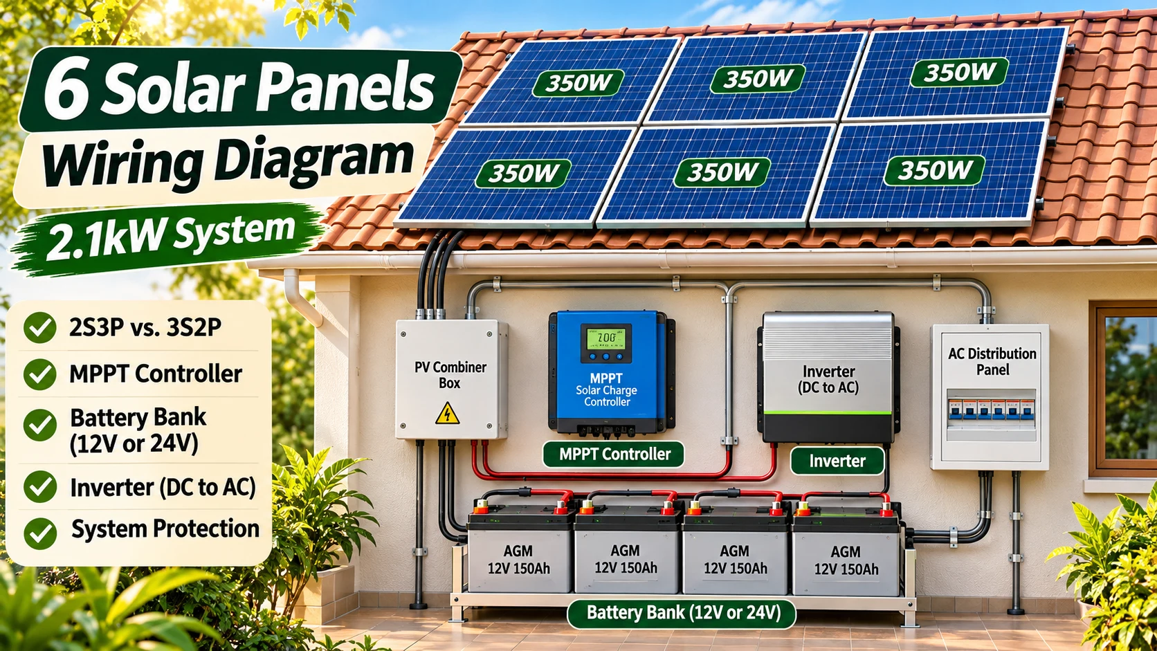
A 6 solar panels wiring diagram helps explain how six photovoltaic modules connect to a charge controller, battery bank, inverter, and electrical loads. With six 350W panels, the combined rated solar capacity is 2,100 watts, or 2.1kW.
But panel wattage alone does not tell you how to wire the array. The correct series-parallel arrangement depends on the panels’ electrical specifications, the MPPT charge controller, battery voltage, inverter requirements, and protection equipment. This guide explains those choices using a practical 2.1kW off-grid example.
6 × 350W Solar System: Quick Facts
- Solar panels: Six modules rated at 350W each.
- Total rated capacity: 2,100W (2.1kW DC).
- Possible configurations: 2S3P, 3S2P, 6S, or 6P, subject to equipment limits.
- Charge controller: An appropriately rated MPPT controller.
- Battery storage: A compatible 12V, 24V, or other supported battery bank.
- Inverter: Selected for AC loads, surge demand, battery voltage, and system compatibility.
- Protection: Equipment-specific fuses, disconnects, bonding, and protective devices.
Key point: Six panels produce 2.1kW of combined nameplate capacity, not a guaranteed continuous 2.1kW output.
FEATURED IMAGE: Insert the verified 1920 × 1080 illustration of six 350W solar panels, an MPPT controller, a battery bank, and an inverter. Use a conceptual equipment layout rather than an unverified terminal-to-terminal wiring diagram.

How Much Power Do Six 350W Solar Panels Produce?
The rated DC power calculation is straightforward:
6 × 350W = 2,100W = 2.1kW
This is the combined nameplate rating under standardized test conditions. Real output varies with sunlight intensity, module temperature, shading, roof angle, dirt, wiring, and conversion losses.
Example Daily Energy Production
A basic planning formula is:
Daily energy (Wh) ≈ Array power (W) × Peak sun hours × Performance factor
For an illustrative calculation using five peak sun hours and an assumed 75% overall performance factor:
2,100 × 5 × 0.75 = 7,875Wh, or about 7.9kWh per day.
This is only a planning example. It is not a verified production forecast for a particular location. Actual usable energy may be lower because of weather, battery charging limitations, inverter losses, battery fullness, and other system conditions.
6 Solar Panels Wiring Diagram: System Overview
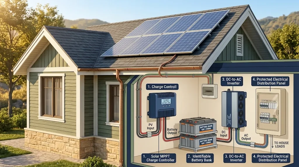
A typical battery-based off-grid solar system follows this basic energy path:
SIX 350W SOLAR PANELS
↓
PV WIRING + REQUIRED DC PROTECTION
↓
MPPT SOLAR CHARGE CONTROLLER
↓
BATTERY BANK + DC PROTECTION
↓
INVERTER (DC TO AC)
↓
PROTECTED AC DISTRIBUTION + LOADS
This is a functional overview, not an installation-ready schematic. A real system needs model-specific conductor sizing, overcurrent protection, disconnects, mounting, grounding, bonding, and other safety equipment.
Electrical safety: Solar modules can generate hazardous DC voltage whenever illuminated. Batteries can deliver extremely high fault currents. Do not use an online illustration as a construction diagram, disconnect energized PV connectors, or open electrical equipment without the necessary training and protection. A qualified solar electrician should design and verify the installation.
Series vs. Parallel Solar Panel Wiring
Solar panels can be arranged in series, parallel, or a combination of both. The arrangement changes the array’s voltage and current, even when the total rated wattage remains 2,100W.
Series Connection
In a series-connected string, panel voltages add while the operating current is approximately the current of one panel, assuming compatible modules and similar conditions.
A longer string can reduce current for a given amount of power, but its voltage may become too high for the charge controller. Cold temperatures can raise open-circuit voltage further.
Parallel Connection
In a parallel configuration, matching string currents add while the voltage remains approximately the same as one string.
Parallel arrangements can produce higher combined current, so conductor capacity, connector ratings, reverse-current protection, and other equipment limits become important.
2S3P vs. 3S2P for Six Solar Panels
Two arrangements frequently considered for six matching panels are 2S3P and 3S2P.
| Feature | 2S3P | 3S2P |
|---|---|---|
| Panels per string | 2 | 3 |
| Parallel strings | 3 | 2 |
| Approx. Vmp | 2 × panel Vmp | 3 × panel Vmp |
| Approx. operating current | 3 × panel Imp | 2 × panel Imp |
| Approx. string Voc | 2 × panel Voc | 3 × panel Voc |
| Total rated power | 2,100W | 2,100W |
2S3P means two panels in each series string, with three matching strings connected in parallel. It gives a lower string voltage and higher total array current than 3S2P, assuming identical modules.
3S2P means three panels in each series string, with two matching strings in parallel. It gives a higher string voltage and lower total array current than 2S3P.
Neither configuration is universally better. The final choice must satisfy the controller’s maximum PV open-circuit voltage, MPPT voltage range, maximum PV current, maximum PV short-circuit current, power rating, and applicable installation requirements.
Design tip: The module’s 350W rating does not reveal its Voc, Vmp, Isc, or Imp. Two different 350W panels may require different string designs.
How to Choose an MPPT Charge Controller
An MPPT solar charge controller manages the transfer of power from the PV array into a compatible battery bank. It operates the panels near their maximum power point while regulating battery charging.
A controller for six 350W panels must be selected using both the PV-side ratings and the battery-side charging limits.
1. Maximum PV Input Voltage
Calculate the total string open-circuit voltage using the panel’s Voc specification and its voltage temperature coefficient. The cold-weather maximum must remain within the controller’s absolute voltage limit.
2. MPPT Operating Voltage Range
The string’s working voltage must remain compatible with the controller’s MPPT operating range under expected conditions. The PV voltage must also provide enough headroom above the battery voltage for charging.
3. Charging Current and Battery Voltage
A 2.1kW array can represent substantial charging current at low battery voltages.
For a purely mathematical illustration, dividing the full 2,100W array rating by 14.4V gives about 146A. Dividing by 28.8V gives about 73A.
These figures are not actual charging-current predictions or controller recommendations. They ignore conversion losses, real panel output, charging limits, battery conditions, and other restrictions. They simply show why battery voltage affects the current handled by the charging system.
A controller with a suitable battery voltage rating may still be too small for the array’s power or current. Some manufacturers allow a certain level of PV oversizing and output clipping, but that must be confirmed for the exact model.
4. Battery Charging Profile
The controller must support the battery chemistry and manufacturer’s required charging profile. AGM, flooded lead-acid, and LiFePO4 batteries have different charging needs.
Battery temperature monitoring, charging-current limits, and battery management system requirements may also affect controller selection.
See the Victron MPPT installation guidance for examples of PV voltage limits and model-specific connection requirements.
12V vs. 24V Battery Bank for a 2.1kW Solar Array
The Pinterest illustration shows AGM batteries but does not provide a reliable connection diagram for the bank. The label “12V/24V” is not enough to establish the actual bank voltage.
As an educational example, consider four identical 12V 150Ah AGM batteries, assuming their manufacturer permits the intended connection arrangement.
| Arrangement | Bank Rating | Nominal Energy |
|---|---|---|
| Four in parallel | 12V 600Ah | 7,200Wh |
| Two series pairs in parallel | 24V 300Ah | 7,200Wh |
Connecting batteries in series increases voltage. Connecting them in parallel increases amp-hour capacity. These methods do not create extra stored energy from the same batteries.
A 24V bank can reduce DC current compared with a 12V bank when delivering the same power, but it requires an inverter and charger designed for 24V operation.
AGM batteries also need balanced connections, appropriate charge settings, and manufacturer-approved installation. A poorly balanced bank can cause uneven charging and shortened battery life.
A nominal 7.2kWh lead-acid bank does not necessarily provide 7.2kWh of practical usable energy. The recommended depth of discharge and other limitations must be considered.
For battery-bank design principles, see Victron’s Battery Bank Wiring Guide.
What Size Inverter Do Six 350W Panels Need?
The inverter converts DC battery power into AC power for compatible household devices. Its size should be based primarily on the AC loads, their simultaneous operation, starting surge, battery system, and inverter efficiency.
A 2.1kW solar array does not automatically require a 2.1kW inverter. A battery-based inverter can deliver more or less than the instantaneous solar output depending on the battery, equipment limits, and available energy.
Example Appliances From the Pinterest Image
| Appliance | Illustrative Power |
|---|---|
| Three LED lights | 30W total |
| Ceiling fan | 100W |
| Television | 150W |
| Total running load | 280W |
If all three loads operate together at these assumed ratings, their combined running power is 280W.
Four hours of operation would require approximately:
280W × 4 hours = 1,120Wh (1.12kWh) of AC energy.
The battery would need to supply more than that because the inverter consumes some energy during conversion. The ceiling fan may also require additional starting power. Actual inverter sizing must account for those factors.
IMAGE 2: Insert the 1200 × 1500 vertical infographic comparing 2S3P and 3S2P solar arrangements, with a conceptual MPPT, battery bank, and inverter overview. Do not show unverified live terminal connections.
Protection, Combiner Boxes, and Disconnects
A complete solar installation needs more than panels, cables, a controller, batteries, and an inverter. Electrical protection must be designed around the actual circuit ratings and applicable electrical requirements.
PV Combiner Box
A combiner box can collect outputs from multiple PV strings into a common circuit. Depending on the system design, it may contain string protection, terminals, disconnecting equipment, and other approved components.
Do not assume every six-panel system requires exactly the same combiner box. The need for string fuses or breakers depends on module ratings, string count, reverse-current conditions, controller design, and applicable electrical requirements.
Battery-Side Protection
Battery circuits can deliver high fault currents. Appropriate DC-rated fuses or circuit breakers, disconnects, conductors, and terminals must be selected for the specific battery chemistry and connected equipment.
A 200A fuse shown in an online diagram is not a universal recommendation. The correct protection depends on the equipment, conductor ampacity, installation conditions, and available fault current.
AC Distribution and Grounding
The inverter AC output must be connected through properly designed distribution and protection equipment. Circuit breakers, ground-fault protection, and neutral-to-ground bonding requirements depend on the inverter design and local electrical rules.
Do not copy green, blue, or brown conductor assignments from a picture without checking the applicable wiring standard. DC system grounding, PV frame bonding, and AC protective earth are related safety functions, but they cannot be treated as interchangeable connections.
For more detailed electrical design principles, consult Victron’s DC Wiring Guidance.
How to Plan a Six-Panel Solar System
Use the following process to prepare a design for professional review. This is a planning checklist, not an instruction to work on energized electrical equipment.
- Collect panel specifications. Record Voc, Vmp, Isc, Imp, temperature coefficients, maximum system voltage, and connector specifications.
- Estimate daily energy demand. List appliances, wattage, operating hours, and starting loads.
- Choose the system architecture. Decide whether the installation needs off-grid battery power, hybrid operation, or another approved design.
- Compare 2S3P and 3S2P. Calculate the array’s electrical characteristics and compare them with MPPT limitations.
- Select battery storage. Consider battery voltage, chemistry, usable capacity, charging limits, and backup duration.
- Check inverter compatibility. Verify battery voltage, continuous output, surge capability, AC frequency, and other model requirements.
- Design electrical protection. Specify appropriate conductors, DC protection, disconnects, bonding, and AC distribution.
- Check the installation location. Evaluate roof structure, mounting hardware, weather exposure, shading, cable routing, permits, and inspections.
- Arrange professional verification. Have the final diagram, equipment selection, and installation checked by a qualified solar electrician.
Common Six-Panel Solar Wiring Mistakes
- Choosing strings from wattage alone: Panel voltage and current specifications determine compatibility.
- Ignoring cold-weather Voc: Low temperatures can raise string open-circuit voltage above controller limits.
- Overloading the MPPT: PV power, charging current, input current, and voltage ratings must all be considered.
- Mixing unsuitable batteries: Different batteries may not share charging and discharging current evenly.
- Assuming 12V and 24V are interchangeable: Inverters and charging equipment must match the battery bank.
- Copying generic fuse sizes: Protection must be selected for the actual circuits.
- Ignoring inverter surge requirements: Motors and other loads can draw more power when starting.
- Using ordinary indoor cable outdoors: PV circuits need correctly rated wiring and connectors.
- Overlooking grounding and bonding: The protective arrangement must match the equipment and applicable code.
- Treating a picture as an installation drawing: A conceptual diagram cannot replace a model-specific electrical design.
Frequently Asked Questions
How many watts are six 350W solar panels?
Six panels rated at 350W each have a combined nameplate capacity of 2,100W, or 2.1kW DC. Real output varies with environmental conditions and system losses.
Is 2S3P or 3S2P better?
Neither is automatically better. A 2S3P arrangement has lower string voltage and higher combined current than 3S2P with identical panels. The correct configuration depends on the module specifications and charge controller limits.
Can six 350W panels charge a 12V battery bank?
Potentially, with a suitably rated charge controller and compatible battery system. However, a 2.1kW array can represent high charging current at 12V. Battery charging limits and controller ratings must be checked.
Is a 24V battery system better for a 2.1kW array?
A 24V bank can reduce DC current compared with 12V at the same power level, but the best voltage depends on the overall design. Every charger, inverter, battery, and connected DC device must be compatible.
Do six solar panels need a combiner box?
Not always. Requirements depend on how the panels are arranged, the number of parallel strings, the module ratings, the controller, and applicable electrical rules. Multiple strings may require appropriate combining and overcurrent protection.
Can a 2.1kW solar system run a television, lights, and fan?
Potentially. A system with a suitable inverter and enough available energy may operate these loads. Actual performance depends on appliance consumption, starting demand, battery capacity, sunlight, and system efficiency.
Can I connect the solar panels directly to an inverter?
Only if the inverter is designed with a compatible solar PV input and its electrical specifications permit the proposed array. A conventional battery inverter does not automatically accept direct PV input. A separate MPPT charge controller may be required.
Final 2.1kW Solar Wiring Checklist
- Confirm all six solar panels are rated at 350W.
- Collect the electrical specifications for the actual panel models.
- Calculate temperature-corrected string voltage.
- Check MPPT input voltage, current, and power limits.
- Confirm the appropriate battery system voltage.
- Verify charging current and battery chemistry compatibility.
- Determine inverter continuous and surge power requirements.
- Specify appropriate DC and AC protection.
- Review PV string protection and disconnect requirements.
- Check grounding, bonding, and required safety devices.
- Confirm mounting, roof structure, cable routes, and weather protection.
- Arrange required permits, inspections, and professional installation review.
The Right Way to Understand a Six-Panel Solar System
Six 350W solar panels provide a total rated capacity of 2.1kW. That is a useful starting point for an off-grid energy system, but it does not determine the safest or most efficient wiring configuration by itself.
Compare possible series-parallel arrangements using the actual panel datasheets. Then select an MPPT controller, battery bank, inverter, wiring, and protection equipment designed to work together.
The best diagram is not simply the one with the cleanest colored lines. It is the one that matches the equipment, electrical limits, installation conditions, and safety requirements of the real system.
For related solar wiring principles, see our 4 × 450W Solar Panel Wiring Guide and 3kW Solar Panel Wiring Diagram.
Technical references: Victron: MPPT Solar Charger Installation, Victron: Battery Bank Wiring, Victron: DC Wiring, and Morningstar: Solar Charge Controller FAQs. These resources explain general principles; always follow the product-specific manuals and applicable electrical regulations.